Schematics
Interconnect Board

Connector and Pin Information: Interconnect Board [PDF]
Common Connector Pinouts
M12 Sensor Inputs
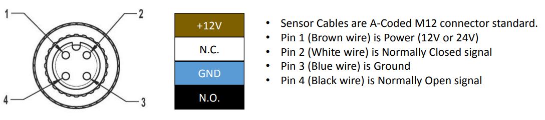
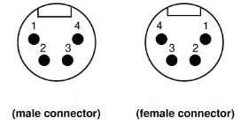
This picture is looking at a Female connector body - pin assignments will be mirrored for Male.
14-pin Control Cable
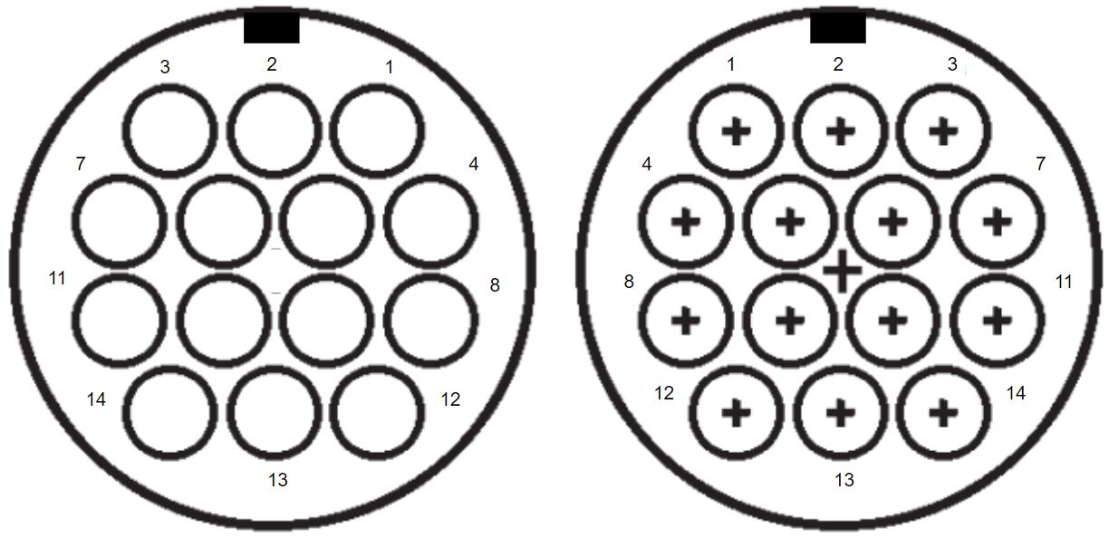
FEMALE connector
MALE connector
Application
- Cables labeled "PLASMA ONLY" are not connected on pins 1 and 2.
- Cables labeled "SPINDLE ONLY" have all pins connected and should not be used for plasma with the EX controller. Doing so will result in poor Torch Height Control performance.
| Connector Pin # | Use | In / Out | Description | Color | CNC12 I/O Assignment |
|---|---|---|---|---|---|
| 1 | Spindle | Digital In | Spindle OK Ground | Blue | IN6 |
| 2 | Spindle | Digital In | Spindle OK | White | IN6 |
| 3 | Plasma | Digital Out | Torch ON | Orange/Black | OUT6 |
| 4 | Plasma | Digital Out | Torch ON | Green/Black | OUT6 |
| 5 | Plasma | Analog In | Voltage Divider (-) | Red/Black | ANLV |
| 6 | Plasma | Analog In | Voltage Divider (+) | Red/White | GND |
| 7 | Spindle | Digital Out | FWD | Orange | OUT5 |
| 8 | Spindle | Digital Out | DCM | Green | OUT5 |
| 9 | Spindle | Analog Out | Analog Control Voltage | Red | AN OUT |
| 10 | Spindle | Analog Out | Analog Common | Black | AN GND |
Pins 11-14 Not In Use
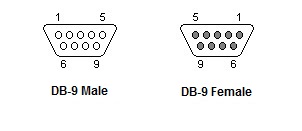
DB9 Motor Connectors
For use with NEMA 23 Motors and Cables
| Pin # | Function | Wire Color |
|---|---|---|
| 1 | Current Set Resistor | N/A |
| 2 | N/C | N/A |
| 3 | N/C | N/A |
| 4 | N/C | N/A |
| 5 | Current Set Resistor | N/A |
| 6 | B + Phase | Yellow |
| 7 | B - Phase | Blue |
| 8 | A + Phase | Red |
| 9 | A - Phase | Green |
XLR Motor Connectors
For use with NEMA 34 Motors and Cables
| Pin # | Motor Phase | Wire Color |
|---|---|---|
| 1 | A + | Red |
| 2 | A - | Green |
| 3 | B + | Yellow |
| 4 | B - | Blue |
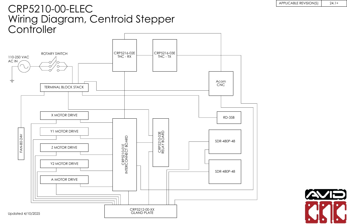
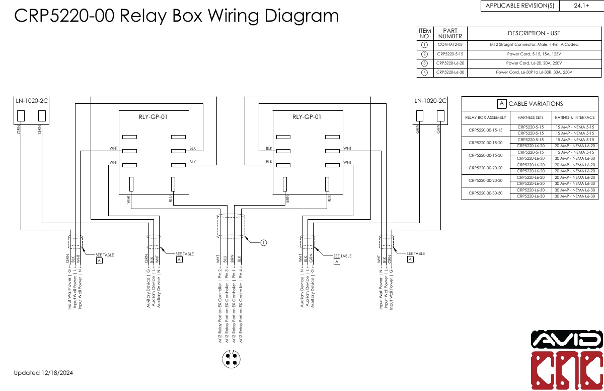
Wiring Diagrams
EX Stepper Controller
Auxiliary Power Relay
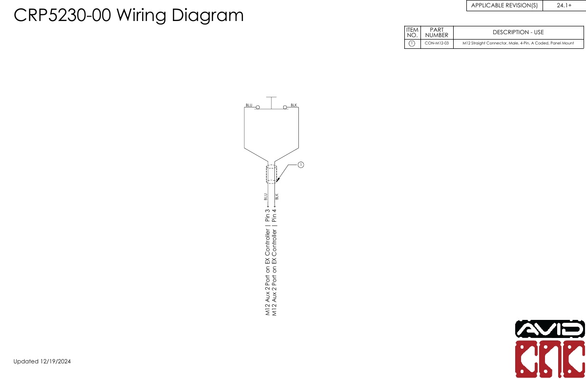
Tool Height Setter